First Steps with Raspberry Pi Pico
The new addition to the growing Raspberry family is the Raspberry Pi Pico. The board is well documented in the PDF Getting Started with Pico. I’m reporting here on my first uses of the board.
Table of content
Installing Development Environment
To get started run the following code. Note you can disable certain aspects of the script, following options exist by running $SKIP_VSCODE, $SKIP_OPENOCD so you can run export SKIP_VSCODE=1 before to not install Visual Studio Code.
wget https://raw.githubusercontent.com/raspberrypi/pico-setup/master/pico_setup.sh
chmod +x pico_setup.sh
./pico_setup.sh
sudo reboot
Trying the examples
To build the examples, follow the instructions in the datasheet and run cmake and then make in the example directory.
Blink example
To make the blink example do the following. I did the building over ssh on a Pi Zero and then copied the resulting binary via scp.
cd ~/pico/pico-examples
mkdir build
cd build
cmake ..
cd blink
make
Drag and drop the resulting blink.uf2 on to the drive that pops up when you plug in a blank pico or when you press the white BOOTSEL button whilst plugin in the device.
Debugging The Little Guy
Lets talk about debugging.
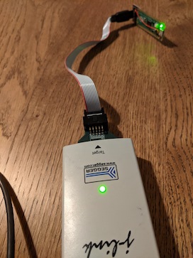
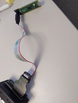
The images above show the finished pcb. On the left the pico is being debugged with a Segger and on the right the pico is being debugged by a pi zero.
Using a Segger Header and a Raspberry Pi
This is my preferred way of debugging. I summarize the theory here and I have ordered a PCB. Once it arrives I will do further testing and talk about it in another blog post. The PCB I made is missing the Vref port. I had to add that in hindsight with a flying wire. Also what I had to realize it only works with the latest versions of segger software. I used a J-Link V10 firmware, a v10.10 J-Link EDU Hardware and a V6.98b Segger DLL / Software to get it running, I tested it in J-Link Commander as can be seen in the screenshot. Then selecting the device type RP2040_M0_1 or RP2040_M0_0 a connection can be established as is seen in the command line log bellow:
Type "connect" to establish a target connection, '?' for help
J-Link>
Unknown command. '?' for help.
J-Link>con
Please specify device / core. <Default>: RP2040_M0_1
Type '?' for selection dialog
Device>
Please specify target interface:
  J) JTAG (Default)
  S) SWD
  T) cJTAG
TIF>S
Specify target interface speed [kHz]. <Default>: 4000 kHz
Speed>
Device "RP2040_M0_1" selected.


Connecting to target via SWD
ConfigTargetSettings() start
J-Link script: ConfigTargetSettings()
ConfigTargetSettings() end
InitTarget() start
InitTarget() end
Found SW-DP with ID 0x0BC12477
DPIDR: 0x0BC12477
Scanning AP map to find all available APs
AP[1]: Stopped AP scan as end of AP map has been reached
AP[0]: AHB-AP (IDR: 0x04770031)
Iterating through AP map to find AHB-AP to use
AP[0]: Core found
AP[0]: AHB-AP ROM base: 0xE00FF000
CPUID register: 0x410CC601. Implementer code: 0x41 (ARM)
Found Cortex-M0 r0p1, Little endian.
FPUnit: 4 code (BP) slots and 0 literal slots
CoreSight components:
ROMTbl[0] @ E00FF000
ROMTbl[0][0]: E000E000, CID: B105E00D, PID: 000BB008 SCS
ROMTbl[0][1]: E0001000, CID: B105E00D, PID: 000BB00A DWT
ROMTbl[0][2]: E0002000, CID: B105E00D, PID: 000BB00B FPB
Cortex-M0 identified.
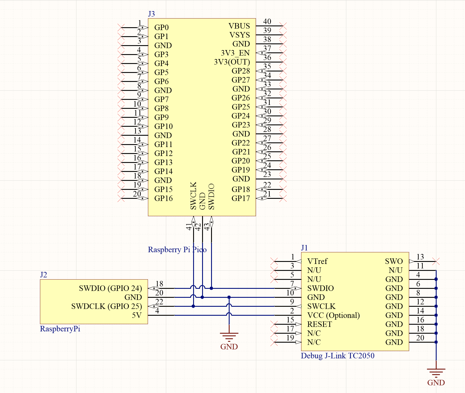
The Pi Pico Side of Things
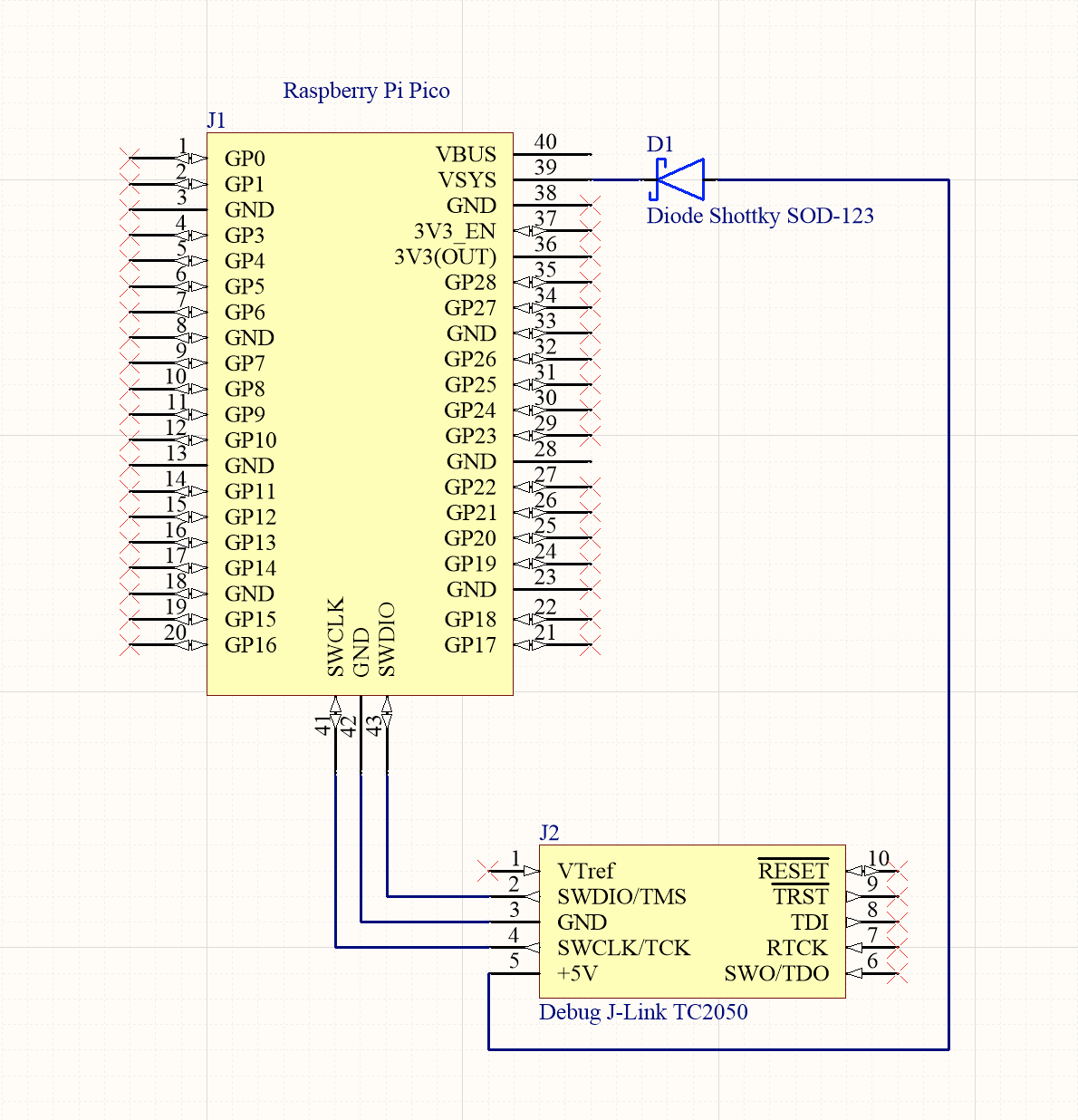
There is no debugging header which is compatible with an existing SWD debugger such as 10 pin header. The board exposes the SWDIO, SWDCLK and GND as reference on the far end of the board. SWO (Serial Wire Output) is not available for RP0240 as it is a feature of ARM M3 and above. The board will have to be powered, this can happen over USB, but will require at least two cables going to the board, which can become a bit of an annoyance. The documentation suggests to use a Raspberry Pi with jumper cables. I decided to make a little adapter PCB to the 10 pin Segger header. The Vsys I made to be attached by a cable via a schottkey diode, as it is on the far end of the pico and I don’t want to cover that space with pcb.
The Pi Side of Things
Next up we need to connect a debug probe either a Pi, Segger or ST-Link (not sure if that’s supported, will have to try it out). Lets start with the Pi and stay loyal to the eco system. The documentation has the following default pinout for the Pi when bitbanging the SWD interface using OpenOCD.
| Raspberry Pi | Raspberry Pi Pico |
|---|---|
| 5V (Pin 4) | Vsys |
| GND (Pin 20) | SWD GND |
| GPIO24 (Pin 18) | SWDIO |
| GPIO25 (Pin 22) | SWCLK |
The Resulting PCB Layout
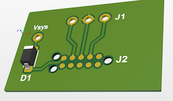
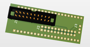
Left: Pi Pico Hat, Right: Pi Hat (note, option is to mount the pi directly on two 20 pin headers)
Using One of the Cores for Debugging
Raspberry Pi Foundation employees in “The Amp Hour Electronics” Podcast #529 mentioned that this is a planned feature for the future. Basically one core debugs the other and debugging is done over USB. A GitHub user has already implemented something in this direction in the repos Pico Debug. This is a very neat solution, as we don’t often need two cores for micro controller projects. It uses ARM’s open source CEMIS-DAP Debugger. At the time of writing, the Pico Debug requires the use of a fork of the pico-sdk which has not been merged. This means pico-debug is not officially supported yet.
WARNING: If you’ve already installed the pico-sdk than this won’t work, you have to uninstall the official version first or change PICO_SDK_PATH.
#!/bin/bash
mkdir pico
cd pico
git clone https://github.com/majbthrd/pico-sdk.git --branch pll_init
cd pico-sdk
git submodule update --init
cd ..
git clone -b master https://github.com/raspberrypi/pico-examples.git
sudo apt update
sudo apt install cmake gcc-arm-none-eabi libnewlib-arm-none-eabi build-essential
cd ./pico/pico-examples
mkdir build
cd build
export PICO_SDK_PATH=../../pico-sdk
cmake -DCMAKE_BUILD_TYPE=Debug ..
cd ./pico/pico-examples/build/picoboard/blinky
make -j4
I used another method to make this build. To build the debug image I used a Debian docker image which I pulled from docker hub to cross compile the binaries. In docker you have to also install apt get install pytho3 git in order for the build to work. This way you don’t have to have to separate sdk’s on your pi with separate paths. You also don’t need a Pi Zero or other Pi to build.
You can download the image for the debug core from the Pico Debug Release Page
Using an Additional Pico as Debugger
Another alternative is to use a second pico with the firmware picoprobe.uf2 on the SWD interface.


